Major Systems and Components of an Automobile:In the previous Units, we learnt about the different types of Automobile. In this Unit, we will discuss the major systems and components of an Automobile.
 |
| Major Systems and Components of an Automobile |
Major Systems and Components of an Automobile
Introduction
In the previous Units, we learnt about the different types of Automobile. In this Unit, we will discuss the major systems and components of an Automobile. An Automobile is made of several components, assemblies and systems. The growing Automotive industry has given rise to a growing auto component industry also.India has emerged as a global outsourcing hub for manufacturing of various Automobile components. All major companies like Toyota, Hyundai, Ford, Volvo, Renault and others are now sourcing their Automotive components from Indian manufacturers.
The auto components industry is predominantly divided into five segments.
- Engine parts
- Drive transmission and steering parts
- Suspension and brake parts
- Electrical parts
- Body and chassis
Session 1: Chassis and Auto Body
Chassis
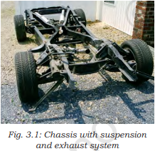
Chassis is a French term and was initially used to denote the frame or main structure of a vehicle. The chassis (Fig. 3.1) contains all the major units necessary to propel the vehicle, guide its motion, stop it and allow it to run smoothly over uneven surfaces. It is the main mounting for all the components including the body. It is also known as the carrying unit.
The chassis includes the following major components.
- A steel frame, which is a major part.
- In case of a passenger car, the whole body is also an integral part of the chassis. However, in commercial vehicles like trucks and buses, the body is not a part of the chassis. Therefore, a chassis is almost a complete vehicle except the body and other accessories, which are not involved in the movement of the vehicle.
- Other major components include engine, transmission system, front and rear axle, steering system, suspension system, wheels, tyres and brakes.
Functions of the chassis
The functions of the chassis includes
- carrying the weight of the vehicle and its passengers
- withstanding the engine and transmission torque and thrust stresses, as well as accelerating and braking torque
- withstanding the centrifugal force while taking a turn and
- withstanding the bending load and twisting due to the rise and fall of the front and rear axles.
Automobile Body or Superstructure
In case of integral or frameless construction, the body is an integral part of the chassis. But, in case of the conventional chassis, the body or superstructure is made after receiving the chassis from the manufacturer. The shape of the body depends upon the ultimate use for which the vehicle is meant.
The body of a car (Fig. 3.2) is made of a sheet of metal or fibre glass, so that passengers can sit in it. To make the journey comfortable, cushioned seats are provided.
The body is provided on all sides with glass panes fixed to protect the passengers from dust and rain.
The body of a bus is made of metal, like
- steel section pillars with steel sheet panelling
- steel section pillars with aluminium panelling and
- all aluminium bodies, i.e., pillars, framework and panelling made of aluminium sections and sheets. This is because aluminium is very light in weight compared to steel.
The body of a truck has the driver’s compartment covered and the rest is kept open. Such bodies are usually called load bodies. In most of the cases, it is an open body, whereas for liquid material like water, milk and fuel products, a tank is mounted on the chassis.
The body is fixed to the chassis with the help of I- or U-bolts with rubber packing placed between the chassis and body cross members .
Requirements of automobile body
The body of a motor vehicle should fulfill certain requirements. It should
- be light weight.
- have minimum number of components.
- have long fatigue life.
- have uniformly distributed load.
- have sufficient space for passengers and luggage.
- have good access to the engine and suspension system.
- have minimum vibrations when the vehicle is running.
- have minimum resistance to air.
- be cheap and easy in manufacturing.
- have clear all-round vision through glass areas.
- have an attractive shape and colour.
Session 2: Engine and Its Components
An engine (Fig. 3.3) is complex unit in which different components are assembled together, and fuel is burned to produce power or energy. The engine converts chemical energy (heat energy) into mechanical energy, which is then utilised for vehicular movement.
There are different processes of fuel combustion. When the fuel is burned within the engine, it is called an Internal Combustion (IC) engine, and when it is burned externally and the produced steam is used for the mechanical movement, it is called an External Combustion (EC) engine. Nowadays, automobile engines are quite economical due to the developments taking place in the field of internal combustion engine.
On the basis of the process of ignition, the automobile engines are classified into spark ignition engine (petrol or gas) and compression ignition engine (diesel). In an IC engine, the reciprocating motion of the piston is converted into rotary motion of the crankshaft and the produced power is then transmitted to move the vehicle. In case of a rotary engine or Wankel engine, the rotor rotates and completes the process of combustion and produces the power, which helps the vehicular movement.
The spark ignition engine can be differentiated from the compression ignition engine as per the following factors.
- The type of fuel used.
- The way the fuel enters in the combustion chamber.
- The way in which fuel is ignited.
Spark Ignition Engine (Petrol or Gas Engine)
The spark ignition engine uses a highly volatile fuel, such as gasoline, which turns into vapour easily. The fuel is mixed with air before it enters in the combustion chamber, and forms a combustible air-fuel mixture .
This mixture then enters the cylinder and getscompressed with the help of a piston. An electric spark is produced by the ignition system which ignites the combustible air-fuel mixture. The combustible gases burn and expand, which forces the piston downwards for generating power .
Compression Ignition Engine (Diesel Engine)
In the compression ignition engine or diesel engine only fresh air enters the cylinder, which is compressed to a very high pressure and temperature, which could go up to 1000°
F (538°
C). The diesel is then injected or sprayed into the engine combustion chamber. This spray contains very fine and tiny particles of diesel in an atomised form. The hot air or heat of compression ignites the fuel and generates the power stroke.
Components of an IC Engine
(1 ) Cylinder:
The cylinder or cylinder liner of an IC engine is fitted in the cylinder block, which is a single casted unit and is considered to be the main body of an engine. The block has cylinder liners. The piston reciprocates up and down from Top Dead Centre (TDC) to Bottom Dead Centre (BDC) to generate power.
The cylinder liner and the cylinder block have to withstand very high pressure (about 70 bar) and temperature (about 700°
C) during power stroke. The material used for the cylinder block must withstand such heat and also disperse it effectively. The cylinder block is well-designed with water passages to remove the excess heat . and separate oil passages are provided for the circulation of lubricating oil. The top portion of the cylinder block is covered by the cylinder head. The crankcase is an integral part of the cylinder block which houses the crankshaft and the lower portion is dipped in an oil pan.
Nowadays, cylinder liners are made of special alloy and internal portion is coated with material like titanium which provides mirror finish and can withstand the wear resistance. The upper end of the cylinder liner has a flange which fits well in the cylinder block. The exterior portion of the cylinder liner is exposed to water jacket for easy dispersion of heat.
( 2 ) Cylinder Head:
The cylinder head is also single casted unit and bolted to the top portion of the cylinder block. The combustion chamber is a part of the cylinder head, where the combustion of gases takes place. The water passages are provided to remove the heat from the cylinder head. In latest engines, the cylinder head also houses the camshaft which has the inlet and exhaust valves with supportive valve mechanism. This provision is made to fix spark plug in SI engines and nozzle in CI engines. The lower portion of the cylinder head is well-machined to ensure there is no leakage of gases. Cylinder head gasket is usually cast as one piece and bolted to the top of the cylinder (engine block). Copper and asbestos gaskets are provided between the cylinder and cylinder-head to obtain a gas-tight joint. The charge enters the combustion chamber through the inlet valve connected to the inlet manifold, and the exhaust gases are removed through the exhaust valves connected to the exhaust manifold.
( 3 ) Piston and Piston Rings:
Piston is a cylindrical unit, used to compress the charge during compression stroke and to transmit the gas force to the connecting rod and then to the crankshaft during power stroke. The pistons of IC engines are usually made of aluminium alloy, which has high thermal conductivity and is light in weight. The material of piston must have the ability for higher heat transfer.
The piston moves up and down (from TDC to BDC) and assists in completing the engine cycle.
The piston rings are placed in the ring groove and provide sealing between the piston and the cylinder liner, thereby preventing the leakage of high pressure gases. These are made of special grade cast iron, which retains its elastic property even at very high temperature. The upper piston rings are called the compression rings and the lower piston rings are called the oiling or oil control rings.
( 4 ) Connecting Rod :
It is usually manufactured by using drop-forged steel. It is made in the shape of ‘I’ so as to reduce its weight and to withstand strength. Its small end is connected to the piston with the help of gudgeon pin and the big end is connected to the crankpin with shell bearings.
It has a passage for the transfer of lubricating oil from the big end bearing to the small end bearing (gudgeon pin).
The major function of the connecting rod is to convert the reciprocating motion of piston to the rotary motion of the crankshaft.
( 5 ) Crank and Crankshaft:
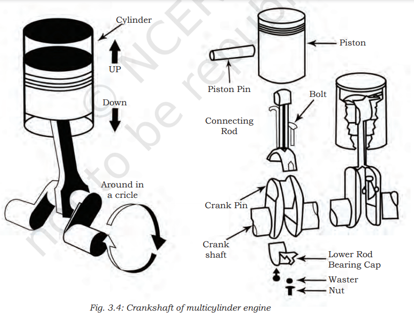
The crankshaft (Fig. 3.4) is called the backbone of an engine because it converts the reciprocating motion of piston into the rotary motion of the crankshaft. The crankshaft is a single casted unit and is made of drop-forged steel main journals which are placed and supported in the crank case. The main journal and connecting journals are machined to a smooth finish to reduce friction and shell bearings are used for smooth rotation of crankshaft.
Front end of the crankshaft will transmit drive to the camshaft and also to the timing gear, whereas the flywheel is bolted to the flange at rear end of the crankshaft.
Main journal of the crankshaft carries the oil passages to lubricate shell bearings.
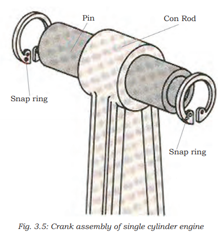
In case of a single cylinder engine crank assembly (Fig. 3.5) is used, two crank webs are connected with the crank pin, and crank webs shafts are press fitted in both. At one side of the shaft magneto is fastened whereas clutch assembly is mounted to the other. The crank assembly is balanced dynamically as well as statically for the smooth transmission of power.
( 6 ) Piston Pin or Gudgeon Pin :
This unit connects the piston and small end of the connecting rod and passes through the piston (Fig. 3.6). Circlips are fitted into recesses in the piston to prevent the gudgeon from touching the cylinder wall. The needle bearing or bronze bushing is press fitted into the connecting rod, due to this the gudgeon pin provides bearing for the oscillating small end of the connecting rod.
( 7 ) Inlet Valve:
The major role of the inlet valve is to submit fresh charge in to the cylinder during the suction stroke. Opening and closing of the valve will control the admission of the charge into the petrol engine or air into diesel engine during suction stroke of an engine. The valve operations will be as per the valve timings. The inlet valve has a wider face or in latest engines two inlet valves are used to maintain volumetric efficiency of an engine.
( 8 ) Exhaust Valve:
The exhaust valve removes out the burnt gases from the combustion chamber after power stroke. The exhaust valve has to bare more heat resistance.
( 9 ) Valve Spring
 |
| Valve Spring |
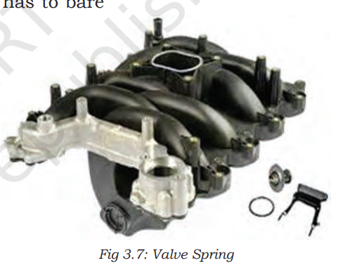
The valve spring (Fig. 3.7)plays an important role to close the valve and also provides air tight compartment to seal the combustible gases during power stroke and also maintain the self-centering movement of the valve. Both ends of the vale spring are machined for smooth function and up and down movements of the valves.
( 10 ) Inlet Manifold:
The fuel air mixture is carried from the carburettor to the cylinder through a separate pipe through inlet manifold in a carbureted engine. Whereas in compression ignition engines (diesel), the air is sucked through the induction manifold. In M.P.F.I the engine holds the throttle body on top of the manifold and the supply of air is monitored by the throttle body sensor.
( 11 ) Exhaust Manifold:
It is a set of pipes and muffler, which is used to remove the exhaust gases from the exhaust ports. Engines oxygen sensors and catalic convertors are used to reduce sound and air pollution, respectively (see Fig. 3.8).
( 12 ) Camshaft:
The major function of the camshaft is to operate the intake and exhaust valves through the cam lobe, the gear drive transmits the power for the rotation of oil pump, therefore the oil pump sucks the oil from the oil sump and transits the same to the oil gallery. The camshaft (Fig. 3.9) is driven by crankshaft at half the speed of the crankshaft.
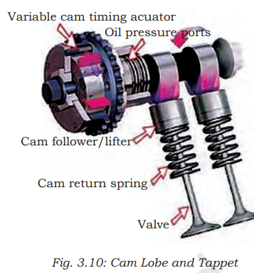
( 13 ) Cam Lobe and Tappet:
The cam lobe (see Fig. 3.10) of the camshaft is placed directly above the bucket tappet, such that the lobe comes around it and pushes down the bucket tappet and the valve, thus opening the valve. In an overhead camshaft with rocker arm, the cam lobe comes under the valve lifter, and causes the rocker arm to rock or turn the lobe and pushes down the valve steam and it moves down to open.
When the cam lobe passes the valve lifter the valve spring retains back to the original length. To close the valve the rocker arm turns back and the valve lifter is pushed down on the cam. In case of double overhead camshaft engine, the double row valves are usually operated by the separate overhead camshaft.
( 14 ) Push Rod and Rocker Arm :
 |
| Push Rod and Rocker Arm |
The motion of the cam lobe pushes the valve lifter upwards. This movement pushes the push rod (Fig. 3.11) and the rocker turns the upward motion of the push rod to the downward movement of the valve stem resulting in opening of the valve .
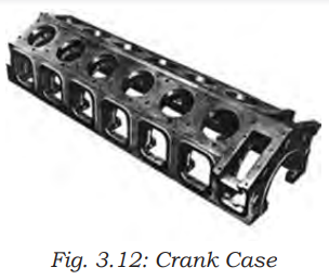
( 15 ) Crank Case:
The crank case is an integrated part of the cylinder block. The casing is provided to hold the crankshaft. The crankshaft is allowed to rotate freely and transmit the power to the flywheel (Fig. 3.12).
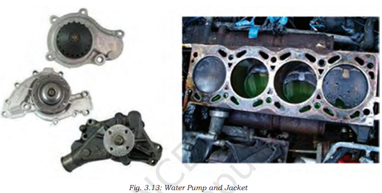
( 16 ) Water Pump and Water Jacket:
The function of water pump is to draw water from the radiator and supply it to the water passages provided in the cylinder block and cylinder head with certain pressure. The circulation of coolant removes the excessive heat from an engine.
This helps in maintaining the engine temperature and also the life of an engine (Fig. 3.13) .
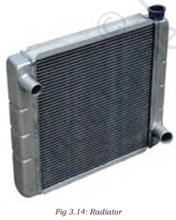
( 17 ) Radiator:
It has two tanks located at the top and bottom. The upper tank is connected to the lower tank with the core through the passages for easy radiation of the heat. The radiator also stores the coolant (Fig. 3.14).
( 18 ) Flywheel:
 |
| Fly wheel |
It is a wheel mounted on the crankshaft which stores the energy during the power stroke and transmits the energy to the transmission system, the clutch and then to the gear box (Fig. 3.15).
( 19 ) Governor:
It is run by drive from the crankshaft. The function of the governor (Fig. 3.16) is to regulate the charge in case of petrol engine and amount of fuel in case of diesel engine to maintain the speed of the engine constant, when the load requirement varies.
The components described above are commonly used for all types of IC engine. Here we are describing only a few components which are used in particular types of engines.
( 20 ) Carburettor:
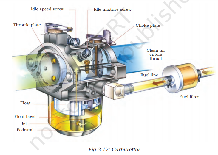
The major function of the carburetor (Fig. 3.17) is to supply carburised fuel as per speed and the engine load. In petrol engines the carburettor is mounted on the induction pipe or on the induction manifold. The quantity of fuel air mixture in appropriate ratio is controlled by the throttle valve and the movements of the throttle valve are connected to the accelerator.
( 21 ) Spark Plug:
The function of the spark plug is to ignite the fuel air mixture after completion of the compression stroke in an engine. It is generally placed in the combustion chamber of the cylinder head. This is only used in petrol engine (Fig. 3.18).
( 22 ) Fuel Injection Pump:
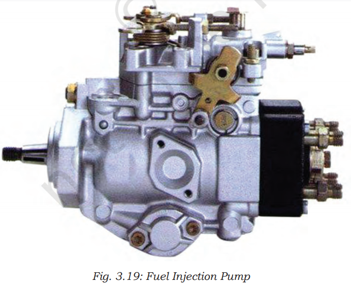
In case of diesel engine the diesel oil from the fuel tank is sucked by the fuel feed pump. The pump first sends the diesel oil to the fuel filter and then to the transfer pump. The transfer pump increase the pressure of the fuel.
The high pressure of fuel is then sent to the distributor rotor through the metering valve and from rotor the fuel is sent to the injector (Fig. 3.19). In case of a multi point fuel injection system, the electric fuel pump is used and placed in the fuel tank. The pump generates the injection pressure and sends it to the fuel filter, and then to the common rail at a pressure of 3 to 4 bar. The common rail or fuel rail is connected to the fuel injector .
( 23 ) Fuel Injector:
The function of fuel injector (Fig. 3.20) is to break the fuel into fine spray (atomised condition) as it enters the combustion chamber of diesel engine.In case of an MPFI engine petrol is injected at the end of compression stroke as the fine spray of the fuel burns more efficiently in the combustion chamber giving better fuel efficiency with less air pollution.









0 Comments