Centrifugal Water Chillers: Centrifugal Water Chillers can also be divided into two types based on the method used to reject heat to the atmosphere: Water Cooled or Air Cooled.
 |
| Centrifugal Water Chillers |
Centrifugal Water Chillers
Centrifugal Water Chillers can also be divided into two types based on the method used to reject heat to the atmosphere: Water Cooled or Air Cooled. Since most Centrifugal Chillers are Water Cooled, they are the primary focus of this clinic. Water Cooled Centrifugal Chillers are generally available from 100 to 3000 tons [350 to 10,500 kW] as prefabricated machines, and up to 8500 tons [30,000 kW] as built-up machines.
components of a Centrifugal Water Chiller
This particular Centrifugal Water Chiller makes use of a shell and tube Evaporator where refrigerant absorbs heat from the water flowing through the tubes. The compressor is made up of 1 or more Centrifugal impellers. A second shell-and-tube heat exchanger serves as the Water Cooled Condenser, where Refrigerant is Condensed inside the shell and water flows inside tubes. Refrigerant is metered through the system using an expansion device such as a fixed orifice plate. An Economizer can be used to enhance the efficiency of a Chiller with multiple Compressor Impellers. A control panel is also provided on the chiller and a starter is either mounted on the Chiller or located remotely. Compressor
 |
| Compressor |
The Centrifugal Compressor uses the principle of dynamic compression, which involves converting energy from one form to another, to increase the pressure and temperature of the refrigerant. It converts kinetic energy to static energy.
Impeller
 |
| Impeller |
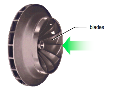
The core component of a Centrifugal Compressor is the rotating impeller. The center, or eye, of the impeller is fitted with blades that draw refrigerant vapor into radial passages that are internal to the impeller body.
Centrifugal Compressor
 |
| Centrifugal Compressor |
The rotation of the impeller causes the refrigerant vapor to accelerate within the impeller passages, increasing its velocity and kinetic energy.
The accelerated refrigerant vapor leaves the impeller and enters the diffuser passages. These passages start out small and become larger as the refrigerant travels through them. As the size of the diffuser passages increases, the velocity, and therefore the kinetic energy, of the refrigerant decreases.
The first law of thermodynamics states that energy is not destroyed—only converted from one form to another. Thus, the refrigerant’s kinetic energy is converted to static energy or static pressure.
Refrigerant, now at a higher pressure, collects in a larger space around the perimeter of the compressor called the volute. The volute also becomes larger as the refrigerant travels through it. Again, as the size of the volute increases, the kinetic energy is converted to static pressure.
Due to its pressure and temperature, the refrigerant leaving the compressor is in a condition that allows its heat to be rejected from the Chiller.
Centrifugal Compressor Energy Conversion
 |
| Centrifugal Compressor Energy Conversion |
Again, in the passages of the rotating impeller, the refrigerant vapor accelerates, increasing its velocity and kinetic energy. As the area increases in the diffuser passages, the velocity, and therefore the kinetic energy, of the refrigerant decreases. This reduction in kinetic energy is offset by an increase in the refrigerant’s static energy or static pressure. Finally, the high pressure refrigerant collects in the volute around the perimeter of the compressor, where further Energy Conversion takes place.
The resulting pressure and temperature of the refrigerant is now high enough that its heat can be rejected from the chiller.
Multistage Compressor
 |
| Multistage Compressor |
Centrifugal compressors use 1 or more impellers to compress the refrigerant. A multistage compressor uses 2 or 3 impellers to increase the pressure of the refrigerant in steps instead of performing the task within a single impeller. Compressed refrigerant vapor travels from the outlet of the first-stage compressor impeller to the inlet of the second-stage compressor impeller. After the accelerated refrigerant vapor leaves the last impeller, it collects in the compressor volute and travels on to the condenser.
Condenser
The high-pressure refrigerant vapor is discharged from the compressor into a heat exchanger that acts as a condenser.
In a water-cooled condenser, water is pumped through the tubes of the shell-and-tube heat exchanger while refrigerant vapor fills the shell space surrounding the tube bundle. A baffle inside the condenser helps distribute the refrigerant evenly. As heat transfers from the hot, high-pressure refrigerant vapor to the water, refrigerant condenses on the tube surfaces.
Cooling water flows first through the lower tubes and then through the upper tubes. This produces a nearly constant temperature difference between the downward-moving refrigerant and the tube surfaces, resulting in a uniform heat transfer rate within the tube bundle .
Condensed liquid refrigerant collects in the bottom of the shell and flows through the liquid line to the expansion devices and Economizer.
expansion device Orifice Plates
 |
| expansion device Orifice Plates |
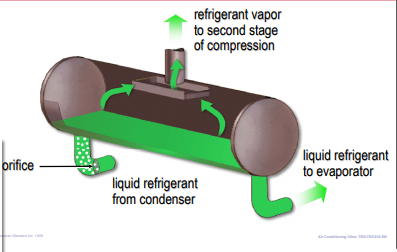
An expansion device is used to maintain the pressure difference between the high-pressure (condenser) and low-pressure (evaporator) sides of the refrigeration system, as established by the compressor. This pressure difference allows the evaporator temperature to be low enough for the refrigerant to absorb heat from the water being cooled, and the condenser temperature to be high enough for the refrigerant to reject heat to water at normally available temperatures. High-pressure liquid refrigerant flows through the expansion device, causing a pressure drop that reduces the refrigerant pressure to that of the evaporator. This pressure reduction causes a small portion of the liquid to boil off, or “flash”, cooling the remaining refrigerant to the evaporator temperature.
The expansion device is also used as a liquid refrigerant metering system, balancing the refrigerant flow rate with the evaporator load condition. In our example centrifugal chiller, the expansion device used is a set of 2 orifice plates. At full load, a large amount of refrigerant is moving through the chiller. The column of liquid refrigerant in the liquid line pressurizes the liquid at its base. During passage through the orifice plates, the liquid refrigerant undergoes a pressure drop equal to the head (H1) before some of it flashes to vapor.
As the load decreases, less refrigerant moves through the chiller and the level of the liquid column drops. Now, as the liquid refrigerant passes through the orifice plates, it only undergoes a pressure drop equal to the lower head (H2) before some of it flashes to vapor. This causes additional flashing at the orifice plate which, in turn, feeds less liquid to the evaporator.
Other types of expansion devices found in centrifugal chillers include: float valves, expansion valves (thermostatic or electronic), and variable orifices.
2-stage chiller Economizer
 |
| 2-stage chiller Economizer |
An Economizer can be used in conjunction with multiple expansion devices to improve the efficiency of a multistage Chiller. In a Chiller with a 2-stage compressor, the expansion process can be separated into 2 steps with an economizer chamber between.
Liquid Refrigerant from the condenser enters the first expansion device, which reduces the pressure of the refrigerant to that of the second-stage impeller inlet. This pressure drop causes a portion of the liquid refrigerant to evaporate, or flash, and the resulting mixture of liquid and vapor enters the economizer chamber. Here, the vapor is separated from the mixture and is routed directly to the inlet of the second stage impeller. The remaining liquid travels on to the second expansion device and Evaporator.
Just before entering the evaporator, the liquid refrigerant flows through a second expansion device that reduces its pressure and temperature to evaporator conditions.
Flashing a portion of the refrigerant prior to the economizer reduces the amount of compressor power required, since the refrigerant vapor generated in the economizer only needs to be compressed by the second-stage impeller.
3-stage chiller Economizer
 |
| 3-stage chiller Economizer |
In a Chiller with a 3-stage compressor, the expansion process can be separated into 3 steps with separate economizer chambers between the steps.
Liquid refrigerant from the condenser enters the first orifice (expansion device), which reduces the pressure of the refrigerant to that of the third-stage impeller inlet. This pressure drop causes a portion of the liquid refrigerant to flash, and the resulting mixture of liquid and vapor enters the high-pressure chamber of the economizer. Here, the vapor is separated from the mixture and is then routed directly to the inlet of the third-stage impeller. The remaining liquid travels on to the second expansion device.
The second expansion device further reduces the pressure of the refrigerant to that of the second-stage impeller inlet. This pressure drop causes a portion of the liquid refrigerant to flash, and the resulting mixture of liquid and vapor enters the low-pressure chamber of the economizer. Here, the vapor is separated from the mixture and routed directly to the inlet of the second-stage impeller. The remaining liquid travels on to the third expansion device and evaporator .
Again, the final expansion device reduces the pressure and temperature of the refrigerant to evaporator conditions.
Evaporator
 |
| Evaporator |
In the flooded shell-and-tube evaporator shown, the low-pressure mixture of liquid refrigerant and refrigerant vapor enters the distribution system that runs the entire length of the shell. Small openings and baffles in the passage of the liquid distributor provide an even spray of refrigerant over the surfaces of the tubes inside the evaporator shell, where the refrigeran absorbs heat from relatively warm water flowing through the tube bundle. This transfer of heat boils the liquid refrigerant on the tube surfaces. The resulting vapor passes through an eliminator that prevents liquid from being drawn upward. The vapor collects in a large chamber at the top of the shell and is drawn back to the compressor. The now-cool water can be used in a variety of comfort or process applications.
Some Chiller designs may make use of a Direct Expansion (DX) shell-and-tube evaporator. In this type of evaporator, liquid refrigerant flows through the tubes and water fills the surrounding shell. As heat is transferred from the water to the refrigerant, the refrigerant boils inside the tubes and the resulting vapor is drawn to the compressor.
Motor
 |
| Motor |
A motor is used to rotate the impeller(s). A direct-drive motor is connected directly to the impeller shaft and the impeller rotates at the same speed as the motor. A gear-drive motor transfers its energy to the impeller shaft using 1 or more sets of gears. This allows the impeller to rotate at a higher speed than the motor.
The direct-drive motor requires fewer bearings and does not incur gear losses. Additionally, since the compressor rotates at a slower speed, it can be much quieter.
Hermetic Motor Cooling
 |
| Hermetic Motor Cooling |
Another important difference in compressor motors is the issue of hermetic versus open. A hermetic motor is totally enclosed within the chiller’s refrigeration system. An open motor is mounted externally—outside of the chiller’s refrigeration system—and uses a coupling to connect the motor and compressor shafts.
The heat generated by the hermetic motor is absorbed by liquid refrigerant, from the liquid line, that flows around, through, and over the motor. The heat must be rejected by the chiller’s condenser.
The heat generated by the open motor is rejected to the air drawn in from the equipment room. This heat must still be rejected from the equipment room, either by mechanical ventilation or, if the room is conditioned, the building’s cooling system. In some designs, this air is simply drawn into the motor housing by the rotating motor shaft. The vent passages tend to get dirty and clog, resulting in higher operating temperatures and hot spots that adversely affect motor efficiency and reliability. Other designs, such as totally-enclosed fancoold (TEFC) and totally-enclosed air-over (TEAO), use a separate fan with a protective housing to cool the motor. They approach the efficiency and reliability of hermetic motors.
Hermetic compressor motors eliminate the need for the shaft couplings and external shaft seals that are associated with open motors. The coupling needs precise alignment, and these seals are a prime source of oil and refrigerant leaks. On the other hand, if a motor burns out, a hermetic chiller will require thorough cleaning, while an open motor will not.
Controls and Starter
 |
| Controls and Starter |
A microprocessor-based control panel is provided on the chiller to provide accurate chilled-water control as well as monitoring, protection, and adaptive limit functions. These controls monitor chiller operation and prevent the chiller from operating outside its limits. They can compensate for unusual operating conditions, keeping the chiller running by modulating system components rather than simply shutting it down when a safety setting is violated. When serious problems occur, diagnostic messages aid troubleshooting .
Modern control systems not only provide accurate, optimized control and protection for the chiller, but can also interface with a building automation system for integrated system control. In a chilled water system, optimal performance is a system-wide issue, not just a matter of chiller design and control.
A starter links the chiller motor and the electrical distribution system. Its primary function is to connect (start) and disconnect (stop) the chiller from line power—similar to what a switch does for a light bulb. The starter, however, handles much more current and must have the appropriate interlocks to work with the chiller control panel and oil pump.
Every electrically driven chiller requires a starter. It must be compatible with the characteristics of both the compressor motor and the electrical circuitry of the chiller. There are many types of starters, including star-delta, across-the-line, auto-transformer, primary reactor, and solid state. A variablespeed drive, which is used to modulate the speed of the motor during normal operation, also serves as a starter. Important characteristics to consider when selecting a starter include first cost, reliability, line voltage, and available current.
Starters
 |
| Starters |
The Starter may be mounted on, or remotely from, the chiller. Use of a unit-mounted starter reduces electrical installation costs. It may also improve reliability and save system design time, since all of the components are pre-engineered and factory-mounted.
Depending on the type of starter selected, there are several options that can simplify installation. Disconnects allow the starter to be isolated from the electrical distribution system, and short-circuit protection can be provided using fuses or a circuit breaker .


