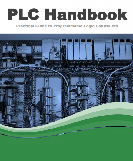
PLC Handbook: Programmable Logic Controllers (PLC) are often defined as miniature industrial computers that contain hardware and software used to perform control functions.
 |
| Programmable Logic Controllers (PLC) |
PLC Handbook
Programmable Logic Controllers (PLC) are often defined as miniature industrial computers that contain hardware and software used to perform control functions.
More specifically, a PLC would be used for the automation of industrial electromechanical processes, such as control of machinery on factory assembly lines, amusement rides, or food processing.
They are designed for multiple arrangements of digital and analog inputs and outputs with extended temperature ranges, immunity to electrical noise, and resistance to vibration and impact.
This PLC handbook consists of 7 chapters as mentioned in the below table.
Contents
- Chapter 1 What is a PLC
- Chapter 2 History of the PLC
- Chapter 3 How to Choose a Controller
- Chapter 4 PLC Hardware
- Chapter 5 PLC Software
- 5-1 Understanding Ladder Logic
- 5-2 Basic Instructions in Ladder Logic
- 5-3 Ladder Logic in Action
- Chapte 6 Practical PLC Topics
- Methods Behind PID Loop Control
- PLC Communication - Coming of Age
- EtherNet/IP: Implicit vs. Explicit Messaging
- Motion Control Explained
- Chapter 7 Collection of PLC Application Stories
A PLC will consist of two basic sections: the central processing unit (CPU) and the Input/Output (I/O) interface system.
Programmable Logic Controllers can range from small modular devices with tens of inputs and outputs (I/O), in a housing integral with the processor, to large rack-mounted modular devices with thousands of I/O, and which are often networked to other PLC and SCADA systems.
The CPU controls all system activity primarily through its processor and memory system. The CPU consists of a microprocessor, memory chip and other integrated circuits to control logic, monitoring and communications.
The CPU has different operating modes. In programming mode the CPU will accept changes to the downloaded logic from a PC. When the CPU is placed in run mode it will execute the program and operate the process.
Input data from connected field devices (e.g., switches, sensors, etc.) is processed, and then the CPU “executes” or performs the control program that has been stored in its memory system. Since a PLC is a dedicated controller it will process this one program over and over again.
DOWNLOAD also MATLAB Programming Fundamentals
The time it takes for one cycle through the program is called scan time and happens very quickly (in the range of 1/1000th of a second, depending on your program). The memory in the CPU stores the program while also holding the status of the I/O and providing a means to store values.
The input/output system is physically connected to field devices and provides the interface between the CPU and its information providers (inputs) and controllable devices (outputs)


0 Comments